Commercial Kitchen Ventilation Designs

Commercial Kitchen Ventilation Designs

Among the frequent questions about designing commercial kitchen ventilation systems are sizing kitchen hoods exhaust and supply air flow rates, kitchen hood designs, fan control strategies, mitigating grease in ductwork, pollution control units and fire protection. In Australia, its requirements are dictated by AS/NZS1668.1 Section 6 and AS1668.2 Section 3. However, there are other standards overseas, such as the International Mechanical Code (IMC), which may be similar in many ways.

There are three main reasons why we need kitchen hoods. The first is obvious. We need to exhaust heat and effluent generated from the cooking process out of the building. The second reason is to ensure safe building conditions, prevent grease buildup, and reduce the risk of a kitchen fire or the building burning down if a kitchen fire does occur.
In our designs, we also want to ensure the hood can contain and suppress any fire outbreak from burning the entire building down. The ultimate goal is to maintain a balanced ventilation system. When we start exhausting a large amount of air from the kitchen, we need make-up air. Otherwise, we are going to end up with a negatively pressurised kitchen. Have you experienced when seated near the entrance when somebody opens the door, there is that massive rush of air gushing in via the entrance? All that means is the kitchen ventilation system design was improper, resulting in the entire space being under negative pressure. To prevent this, we want to keep those kitchen exhausts and make-up supply airflow differential as low as possible. It is also to help ensure the kitchen ventilation system minimises the building’s overall HVAC load. That’s why selecting the type and size of a kitchen hood is critical.

AS1668.1 Section 6

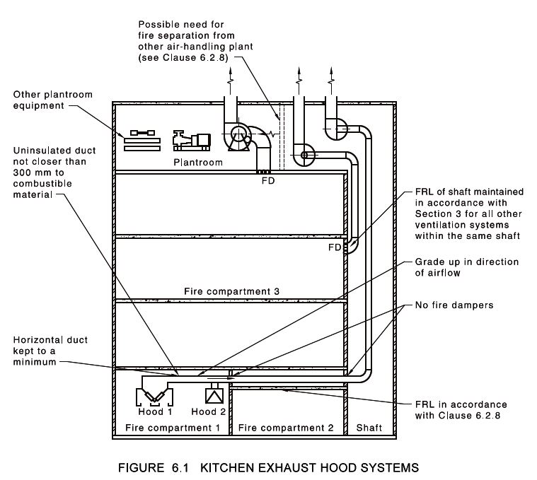
Where the kitchen exhaust hood systems are used to assist smoke control, the kitchen exhaust systems must not serve more than one fire compartment.


Kitchen exhaust ducts serving two different fire compartments must not share the same shaft.


All minor supply and exhaust ducts sharing a shaft with the kitchen exhaust ducts must have fire dampers when penetrating the shaft walls. It is to maintain compartmentation as fire may spread between the ducts.


Kitchen exhaust ducts must be at least 1.2mm thick galvanised steel or not less than 0.9mm thick stainless steel when not enclosed in dedicated fire-resistance shaft required by the National Construction Code and -/60/60.


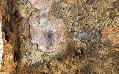
Button punch snap-lock joints must not be used.
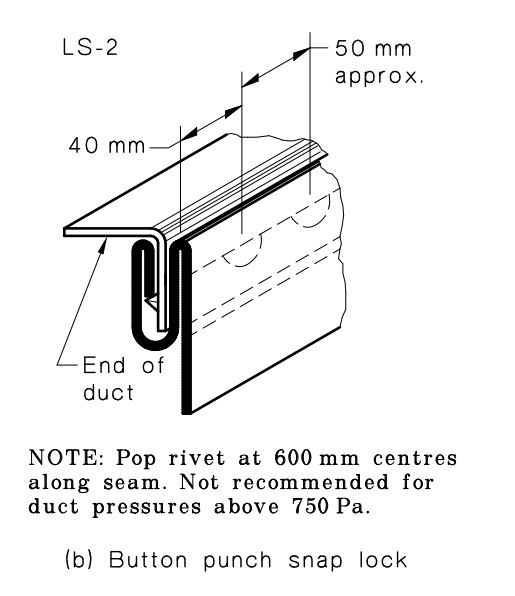
button punch snap lock

Kitchen exhaust ducts when installed horizontally shall have a rise of not less than 5% in the direction of air flow. As much as possible install kitchen exhaust duct vertically. At each change of direction in the horizontal runs ducts access panel must be provided at every 3m. 

A drain must be provided at the lowest point of each run of ducting.

Kitchen exhaust ducts must not be closer than 300mm (12 inches) to any combustible materials or to insulate to achieve -/30/30 FRL.

Kitchen exhaust ducts penetrating floors, walls, ceiling/ floor or ceiling/ roof into another compartment must be enclosed in fire-resisting constructions as fire damper are not allowed in kitchen exhaust systems.

Kitchen exhaust fans and cowls installed within the building envelope must not be deemed combustible and have fusing temperature above 1,000°C.

Operation during fire mode

The kitchen exhaust fans must continue to run during fire mode, the supply air fans may stop if the supply air adversely affect the smoke layer. When the adjoining space to kitchen is within the same compartment, the kitchen exhaust system may be used for smoke control. As the kitchen will be under negative pressure.

A warning label as below must be installed at the kitchen exhaust system.

WARNING: THIS VENTILATION SYSTEM SHALL NOT BE TURNED OFF DURING A FIRE.

When the air handling plant for the kitchen is not within the same compartment as the kitchen, it must be enclosed within and FRL to maintain compartment integrity. Where other plant serving other compartments, all associated ducts must also be in fire-resisting constructions.
If the length of the exhaust duct exceed 10m and exposed flame or ember is part of the cooking process, UL1046 UL Standard for Safety Grease Filters for Exhaust Ducts must be provided.

Wood fired ovens or similar that produces sparks must be provided with spark arrestors at the connection to the duct.

AS1668.2 Section 3.4

This section of the AS1668.2 and Appendix E spell out the requirements for the seven most common types and configuration of kitchen hoods. 

Hood Types
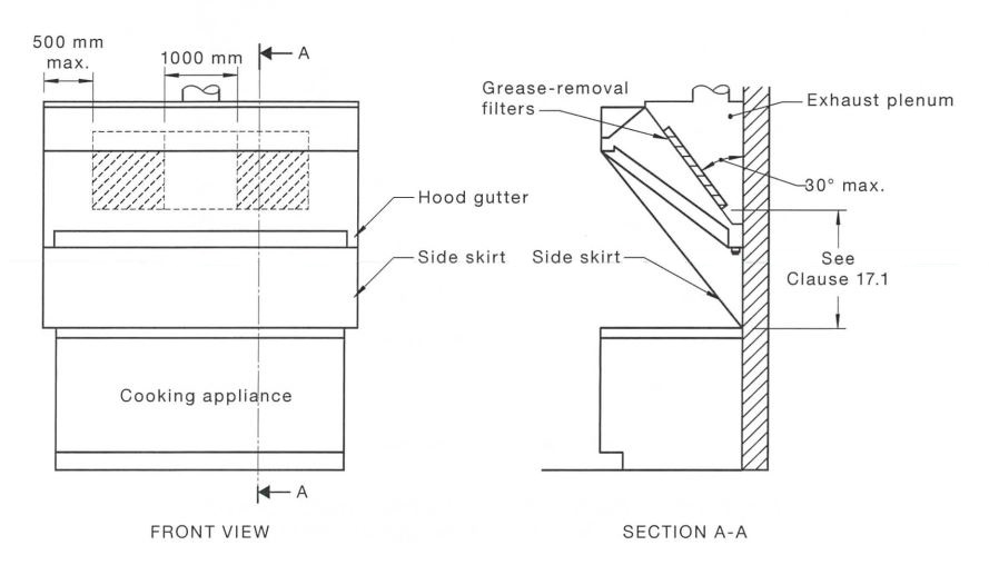
AS1668.2 kitchen exhaust E3 Hood Type 1 Low sidewall

(a) Hood Type 1 Low sidewall where the canopy does not extend at least 150 mm beyond the edge of the cooking surface (see Figure E3, Appendix E).
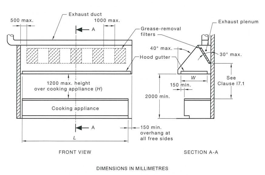
(b) Hood Type 2 Corner-mounted, subject to a maximum length to width ratio of 2:1 (see Figure E4, Appendix E).
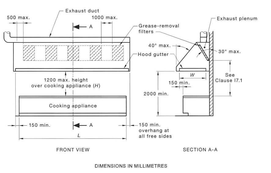
AS1668.2 kitchen exhaust hood E5 type 3 side wall with grease removal

(c) Hood Type 3 Sidewall (see Figure E5, Appendix E).
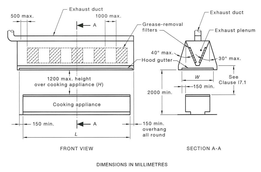
(d) Hood Type 4 Island (see Figure E6, Appendix E).
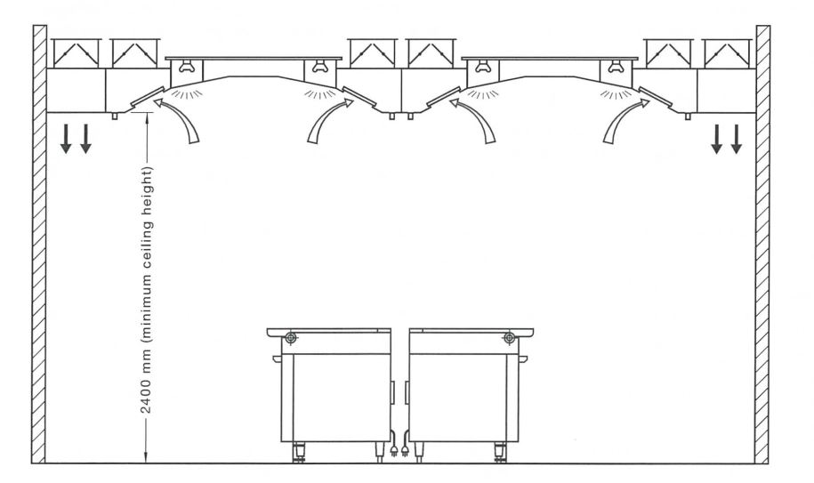
(e) Hood Type 5 Ventilated ceiling (see Figure E12, Appendix E).
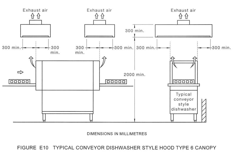
AS1668.2 kitchen exhaust hood E10 type 6 conveyor dishwasher style hood

(f) Hood Type 6 Dishwasher Style hood (see Figure E10, Appendix E).

(g) Hood Type 7 Proprietary equipment.

Cooking process type

(a) Process Type 1 Non-grease-producing equipment and void spaces under the hood, which serve to ventilate other cooking equipment.
(b) Process Type2 Low-grease, medium-heat-producing equipment such as griddles, ranges, salamanders, conventional fryers, tilting Skillets, steam kettles, gas ovens and induction cookers.
(c) Process Type 3 High-grease, low-heat-producing equipment such as electric deep-fat fryers, grooved griddles, hot tops and hot top ranges.
(d) Process Type 4 High-grease, medium-heat-producing equipment such as countertop barbecues and gas-fired deep fat fryers.
(e) Process Type5 High-grease, high-heat-producing equipment, and open flame charcoal equipment utilizing solid fuel.
(f) Process Type 6 Oriental cooking tables and/or woks.
(g) Process Type 7 Bread ovens and steam-producing combination ovens.

Kitchen hood over non-grease producing equipment

If the equipment does not product grease such as dish-washers, then grease filters are not required but the exhaust face velocity of the kitchen hood must be more than 0.3m/s.

If an overhangs on all sides of at least 300mm with minimum height of 300mm and contained hood volume no less than 0.3m3, then the face velocity may be reduced to no less than 0.1m/s. 

Charcoal and solid fuel appliances

Charcoal and solid fuel appliance can not share the same hood with grease or oil-generating appliances. The exhaust from charcoal and solid fuel appliances, its exhaust will need to be treated to reduce contaminants. It must be kept below the max limit specified by the local councils.

Kitchen exhaust air flow rates (Q)

When calculating the hood exhaust flow rate required, we will need to take the worst case application to determine the total airflow rate needed. Say, we have a Type 4 coking process under the same hood as a Type 2 cooking process, we will need to base our calculation on the Type 4 cooking process.

Under no circumstances that the exhaust airflow rate be less than 250L/s/m2 of cooking surface.

The calculation in the table below are based on the minimum overhand distance noted.
The hood overhand for Type 1 to 4 cooking process must not be less than 150mm.
Type 5 cooking process must not be less than 300mm overhang.
Type 6 and 7 cooking processes must not be less than 450mm overhang.

Under no circumstance that the length of the cooking appliances be more than the kitchen hood length.
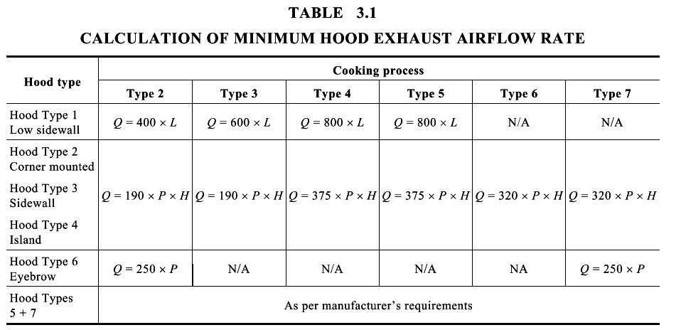
figure 3.1 calculation of minimum hood exhaust airflow rates
where
Q = exhaust airflow rate, in litres per second
L = inside length of hood, in metres
W = inside width of hood, in metres
P = inside perimeter of hood over all exposed sides, in metres
H = height of hood above cooking appliance, in metres

Calculation of inside perimeter (P)
Hood Type 2 Corner mounted P = W + L
Hood Type 3 Sidewall P = 2 W + L
Hood Type 4 Island P = 2 W + 2L
Hood Type 6 Eyebrow P = 2 W + 2L

Requirements

Some essential points here need to be recognised. The first is that the exhaust fan for a kitchen hood needs to turn ON automatically whenever kitchen appliances are ON. That means you can’t just use a wall switch to turn the exhaust fan on and off anymore. It needs to turn ON when any cooking is happening automatically. You can’t just run the fan to a wall switch because the standard doesn’t allow it. It means that the supply fan or the makeup air unit must also interlock with the exhaust fan. So when the exhaust fan turns ON due to cooking, the makeup air unit must also turn ON.

Secondly, hoods need to install with an 450mm (18 inches) clearance to combustibles. We’re all familiar with the code requirement that grease ductwork requires an 18-inch clearance to combustibles, or we need to wrap it with insulation or fire wrap. We need to look at the hood as an extension of that grease ductwork if there are any combustible material within 450mm (18 inches) of the hood in all direction, including wood stud walls.

Third, all hoods require at least 150mm (6 inches) of overhang over each cooking appliance on all open sides. It means the hood must extend at least 150mm (6 inches) beyond the cooking appliance on both sides and the front, assuming we have a hood mounted up against the wall. The most common kitchen hood depths are 1370mm and 1500mm (54 and 60-inch).
We need to ensure that 150mm (6 inches) of front overhang for code are met and exceeded. We typically aim for 450mm to 600mm (18 to 24 inches) of front overhang to ensure properly capturing the grease heat and smoke. The height of the hood is typically 600mm (24 inches) tall but is sometimes extended to 750mm (30 inches) if space is available. If we have the area, we’d like to make that hood as large as possible because the oversized hood has a larger capture volume, typically requiring lower exhaust airflow. In addition, it will allow us to use smaller exhaust fans, smaller makeup air units and less energy, so we would have less upfront cost and lower energy.
Let’s look at some of the clearance to combustible reduction methods. Suppose we know there will be combustible materials anywhere near one side or multiple sides of the hood. In that case, we can add a one-inch layer of insulation from the factory to that side of the hood, which would then need zero-inch clearance to the combustibles. Adding this in the field is rather complicated and expensive, so when selecting the hood, we need to ask questions like is there a wall to the left or the right of this hood, and what is that wall made. It is to avoid that at all costs.
If we were designing a kitchen hood from scratch, the first thing we would have to do is determine the size of the hood. So as we just reviewed, the size of the hood depended on the kitchen appliances beneath the hood. So, in addition to dictating the physical size of the hood, the kitchen appliances also dictate the exhaust airflow rate required from that hood. So when discussing exhaust airflow rates concerning kitchen ventilation systems, we always look at the airflow rates in terms of the airflow rates per linear foot of hood. Therefore, if we had a 95L/s per 300mm (200 cfm per foot) exhaust airflow rate and a 3m (10-foot long hood), 95L/s times 0.3m require 950L/s (2,000 cfm) of total exhaust airflow.

Some manufacturers can take exception to the requirements due to their hood designs and testing, so when it goes through the listing and testing, as you see in red on this chart, the airflow rates may be significantly lower than what the code requires. When designing and installing a kitchen ventilation system, some hood manufacturers will allow you to make exceptions to the code. They have recommended exhaust airflow charts, which you can use. These values are in cfm per linear foot of hood.

You must consistently base your airflow on the cooking appliance that requires the most exhaust airflow. For example, a charbroiler or a wok requires significantly more exhaust airflow than an oven or a steamer would. If you had a char broiler in a lineup because that produces a lot of heat and grease and smoke, and if you had a char boiler in a line up next to some griddles or fryers, you’re still going to base the overall hood’s exhaust air flow rate on the airflow rate recommended for that char broiler because it is the heaviest duty appliance.
When selecting the proper exhaust air flow rate, if we have an appliance lineup that totals 1950mm (78 inches) in length and then we take into account that six inches of overhang required by code, sometimes you may get bigger, but for this case, let’s assume we’re going with the codes. To satisfy the code that, six inches of side overhang means we need at least a 2250mm (90 inches) long. So if we take this hood, we multiply it by the airflow rate required by our heaviest duty appliance. This is where we would use a total exhaust airflow of 750L/s (1875 cfm). So hopefully, that makes sense to everybody, especially if you get pulled into a design-build application where you’re going to size that hood.
Let’s now take a look at supply or, as we call it, makeup air as it relates to the kitchen exhaust applications, so what you see here are two main ways we introduce supply air to a kitchen hood. As we always want to maintain a little bit of negative pressure at the hood, we want to supply just a little less than what is being exhausted. Usually, we should bring in a 20% gap between the supply and exhaust airflows via other means or from the same makeup air unit but away from the kitchen hood. That is to maintain just that slight negative pressure at the hood. Now when we supply or size that supply air plenum, we do it in a very particular fashion so that the velocity of the air just barely makes it to the bottom lip of that hood, so in an ideal scenario. We don’t want any supply air introduced via that plenum going out into the space and the kitchen. We want all that supply air pulled straight back out of the hood. This way, the kitchen ventilation system is self-isolated or isolating itself from the rest of the building’s heating and cooling loads.
The makeup air is not there to help keep anyone cool. Instead, we have that supply air plenum mounted to the front to ensure that most of that air is pulled straight back out of the hood.

The most common question regarding untempered air is the international mechanical code requires that all makeup air systems start and operate automatically with the exhaust fan. We can accomplish that with heat detectors and control panel.

Related

Scroll to Top