J5.4 Fan systems
J5.4 Fan systems
(a) Fans, ductwork and duct components that form part of an air-conditioning system or mechanical ventilation system must—
(i) separately comply with (b), (c), (d) and (e); or
(ii) achieve a fan motor input power per unit of flowrate lower than the fan motor input power per unit of flowrate achieved when applying (b), (c), (d) and (e) together.
[In other words, there are two ways for compliance (i) to simply show each component of the system individually are more efficient or (ii) the whole system is more efficient than a system designed to meet the individual component efficiency. This will increase compliance flexibility without the need for JV3 calculation.]
(b) Fans—
(i) Fans in systems that have a static pressure of not more than 200 Pa must have an efficiency at the full load operating point not less than the efficiency calculated with the following formula:
ηmin = 13 x ln(p) – 30
where—
ηmin = the minimum required system static efficiency for installation type A or C or the minimum required system total efficiency for installation type B or D; and
p = the static pressure of the system (Pa).
(ii) Fans in systems that have a static pressure above 200 Pa must have an efficiency at the full load operating point not less than the efficiency calculated with the following formula:
ηmin = 0.85 x (a x ln(P) – b + N) / 100
where—
ηmin = the minimum required system static efficiency for installation type A or C or the minimum required system total efficiency for installation type B or D; and
P = the motor input power of the fan (kW); and
N = the minimum performance grade obtained from Table J5.4a; and
a = regression coefficient a, obtained from Table J5.4b; and
b = regression coefficient b, obtained from Table J5.4c; and
ln = natural logarithm.
(iii) The requirements of (i) and (ii) do not apply to fans that need to be explosion proof.
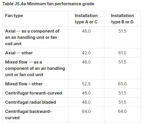
Table J5.4a Minimum fan performance grade
Notes to Table J5.4a:
1.Installation type A means an arrangement where the fan is installed with free inlet and outlet conditions.
2.Installation type B means an arrangement where the fan is installed with a free inlet and a duct at its outlet.
3.Installation type C means an arrangement where the fan is installed with a duct fitted to its inlet and with free outlet conditions.
4.Installation type D means an arrangement where the fan is installed with a duct fitted to its inlet and outlet.
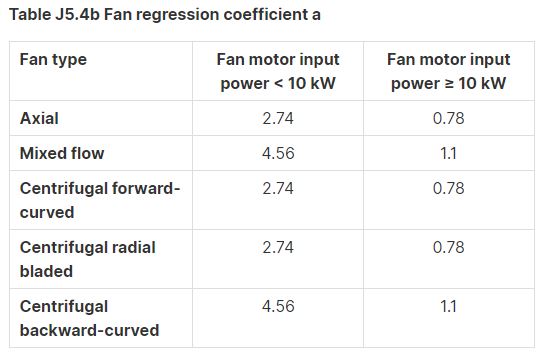
Table J5.4b Fan regression coefficient a
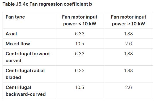
Table J5.4c Fan regression coefficient b
(c) Ductwork—
(i) The pressure drop in the index run across all straight sections of rigid ductwork and all sections of flexible ductwork must not exceed 1 Pa/m when averaged over the entire length of straight rigid duct and flexible duct. The pressure drop of flexible ductwork sections may be calculated as if the flexible ductwork is laid straight.
[ASHRAE recommended 0.8 Pa/m since the late 1990 for optimum material use against energy use.]
(ii) Flexible ductwork must not account for more than 6 m in length in any duct run.
(iii) The upstream connection to ductwork bends, elbows and tees in the index run must have an equivalent diameter to the connected duct.
[Ductwork bends that have a smaller effective diameter than the upstream is disallowed.]
(iv) Turning vanes must be included in all rigid ductwork elbows of 90° or more acute than 90° in the index run except where—
(A) the inclusion of turning vanes presents a fouling risk; or
(B) a long radius bend in accordance with AS 4254.2 is used.
[Preference is to use long radius bend to avoid the use of turning vanes, turning vanes can prevent effective duct cleaning unless access panels are provided on both sides of the vanes.]
(d) Ductwork components in the index run—
(i) The pressure drop across a coil must not exceed the value specified in Table J5.4d.
[Max coil pressure drop]
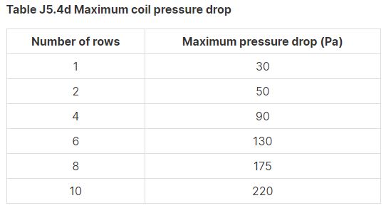
Table J5.4d Maximum coil pressure drop
(ii) A high efficiency particulate arrestance (HEPA) air filter must not exceed the higher of—
[Max filter pressure drop]
(A) a pressure drop of 200 Pa when clean; or
(B) the filter design pressure drop when clean at an air velocity of 1.5 m/s.
(iii ) Any other air filter must not exceed—
(A) the pressure drop specified in Table J5.4e when clean; or
(B) the filter design pressure drop when clean at an air velocity of 2.5 m/s.
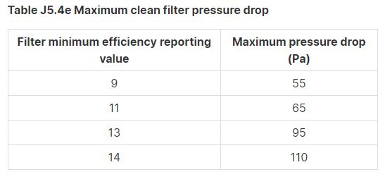
Table J5.4e Maximum clean filter pressure drop
(iv) The pressure drop across intake louvres must not exceed the higher of—
[Max louvre pressure drop]
(A) for single stage louvres, 30 Pa; and
(B) for two stage louvres, 60 Pa; and
(C) for acoustic louvres, 50 Pa; and
(D) for other non-weatherproof louvres, 30 Pa.
(v) The pressure drop across a variable air volume box, with the damper in the fully open position, must not exceed—
[Max VAV pressure drop]
(A) for units with electric reheat, 100 Pa; and
(B) for other units, 25 Pa not including coil pressure losses.
(vi) Rooftop cowls must not exceed a pressure drop of 30 Pa.
[Max cowl pressure drop]
(vii) Attenuators must not exceed a pressure drop of 40 Pa.
[Max silencer pressure drop]
(viii) Fire dampers must not exceed a pressure drop of 15 Pa when open.
[Max fire damper pressure drop]
(ix) Balancing and control dampers in the index run must not exceed a pressure drop of 25 Pa when in the fully open position.
[Max damper pressure drop]
(x) Supply air diffusers and grilles must not exceed a pressure drop of 40 Pa.
[Max diffuser pressure drop]
(xi) Exhaust grilles must not exceed a pressure drop of 30 Pa.
[Max grille pressure drop]
(xii) Transfer ducts must not exceed a pressure drop of 12 Pa.
[Max transfer duct pressure drop]
(xiii) Door grilles must not exceed a pressure drop of 12 Pa.
[Max door grille pressure drop]
(xiv) Active chilled beams must not exceed a pressure drop of 150 Pa.
[Max chilled beam pressure drop]
(e) The requirements of (a), (b), (c) and (d) do not apply to—
(i) fans in unducted air-conditioning systems with a supply air capacity of less than 1000 L/s; and
(ii) smoke spill fans, except where also used for air-conditioning or ventilation; and
(iii) the power for process-related components; and
(iv) kitchen exhaust systems.
Read more: BCA Part J5.5 Ductwork insulation
Read more: BCA Part J5.8 Pipework insulation
Read more: BCA Part J5.6 Ductwork sealing
Read more: BCA Part J5.9 Space heating
Read more: BCA Part J5.7 Pump systems
Read more: BCA Part J5.10 Refrigerant chillers
Read more: BCA Part J5.12 Heat rejection equipment
Related
Read more: Fan wall
Read more: How to verify the percentage of outside air in an enclosure
Read more: BCA Part J5 Air-conditioning system control
Read more: Microbial Induced Corrosion (MIC) in Pipes
Read more: Is your kitchen exhaust system a fire hazard
Read more: What is coanda effect
