What is an Air Conditioner Evaporator Cooling Coil
What is an Air Conditioner Evaporator Cooling Coil
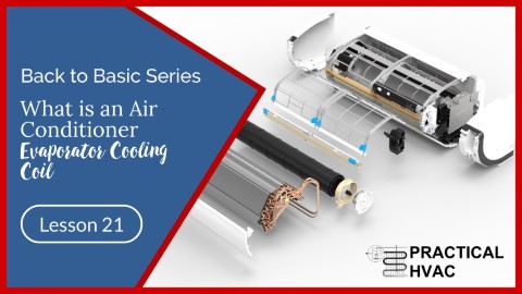
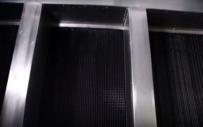
The evaporator is a heat exchanger that operates on the same principles as the condenser. Its function is to allow the best possible exchange of heat between the air of the room and the refrigerant flowing inside the equipment pipework.
The ambient air gives up its heat to the refrigerant as it passes over the evaporator. The refrigerant then vapourises as it absorbs the heat from the air while it cools.
As with the condenser, the refrigerant and air are in counter-current flow, so the heat exchange is optimised.
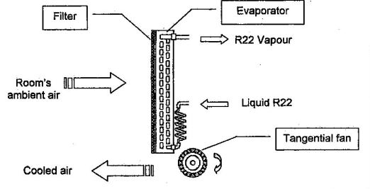
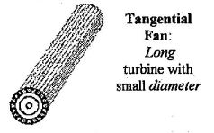
The indoor hi-wall unit uses a barrel tangential fan that circulates the air in the air-conditioned room. It works on the same principle as a paddle wheel.
This type of fan, with a long turbine of a small diameter, is particularly appropriate for small comfort air conditioning because it is very quiet.
The ambient air passes through a filter before moving on over the evaporator. This filter should always be kept perfectly clean. Just remember that a clogged-up filter is the origin of many faults. Most walls hi-wall split air conditioners come with polypropylene filter mesh that will require regular cleaning.
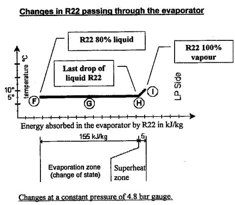
We’ll use this diagram and symbols to study how the refrigerant passes through the evaporator.
Firstly, remember that the LP is the same at all points on the low-pressure side. We also know that refrigerant emerges from the capillary expansion devices as saturated vapour as a mixture of 80% liquid and 20% vapour.
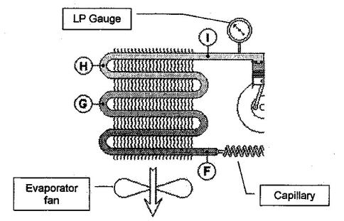
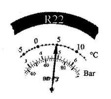
Now let’s assume that the LP gauge shows a pressure of 4.8 bar.
The pressure-temperature relationship for R22 marked on the gauge confirms that at a pressure of 4.8 bar, the evaporation temperature of R22 is 5°C. That is, the evaporation step takes place at this temperature.
The temperature in the room to be air-conditioned is well above 5°C. Therefore, there should be no problems with cooling the air!
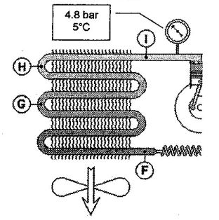
Now let’s take our diagram and examine in more detail the state of the refrigerant at various points in the LP circuit.
At point F, the R22 vapour and liquid mixture emerges from the capillary expansion device. Its pressure is 4.8 bar, and its temperature of 5°C.
We’re going to follow the changes that take place in the refrigerant with the help of a diagram.
Note: Don’t be too concerned about the exact percentages of liquid and vapour at the capillary outlet. It varies according to the operating conditions.
To simplify things as much as possible, the bigger the temperature difference between the capillary inlet and outlet, the colder the liquid should become. To cool the liquid further, we must remove more heat from it. We must then vaporise more liquid.
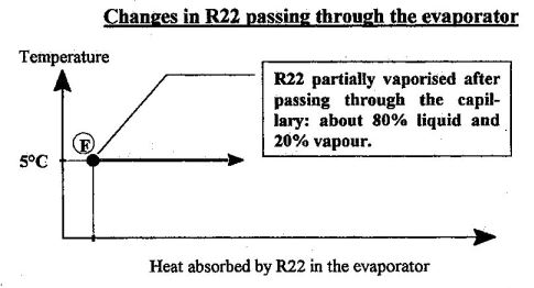
What is important to remember is that the refrigerant emerges from the capillary at low pressure and low temperature, ready to absorb heat from its surrounding that is hotter than itself, particularly from the air of the room is air-conditioned. It is the primary aim of an air conditioning system.
From point F to point H
From point F to point H, the R22 is always on the evaporation step at 5°C.
Whilst flowing through the evaporator, the refrigerant at 5°C gradually absorbs heat from the room’s warm air as it sweeps over the evaporator.
As the refrigerant is on the evaporation step, its temperature stays constant, and all the heat absorbed from the air is entirely used to vaporise the liquid. So there is more and more vapour and less and less liquid. The air is cooled as this happens.

Let’s look at point G, somewhere close to the middle of the evaporator. What temperature do you think that a thermometer placed at this point would show?
Point G is in the middle of the evaporator, where the R22 is at its evaporation step. Therefore, a thermometer at G would read 5°C, the same temperature indicated by the LP gauge located at the suction side of the compressor.
So as it moves along the evaporator, the refrigerant vaporises by absorbing heat from the air. So there will be more and more vapour, and less liquid is present.
At point H, the last droplets of liquid vaporise. This point is right at the end of the evaporation step, and there is entirely 100% vapour present at 5°C.
No more liquid is present at H, but we’re not at the end of the evaporator yet. As warm air still passes over the evaporator, will the vapour at 5°C absorb some more heat? Since there is no change of state step and no latent heat. The temperature of the vapour will rise. As for the pressure, it will remain the same as throughout the rest of the evaporator.
Let’s look at point G, somewhere close to the middle of the evaporator. What temperature do you think that a thermometer placed at this point would show?
Point G is in the middle of the evaporator, where the R22 is at its evaporation step. Therefore, a thermometer at G would read 5°C, the same temperature indicated by the LP gauge located at the suction side of the compressor.
From Point H to point I
At H, the refrigerant exists as 100% vapour at a pressure of 4.8 bar.
The air in the room is a lot warmer than the vapour and is still passing over the evaporator, so the temperature of the vapour continues to increase until we reach the point I.
The vapour is superheated relative to the evaporation temperature, which is the reference temperature for the LP side. The temperature difference between the refrigerant temperature at the evaporator outlet and the evaporation temperature is called the superheat.
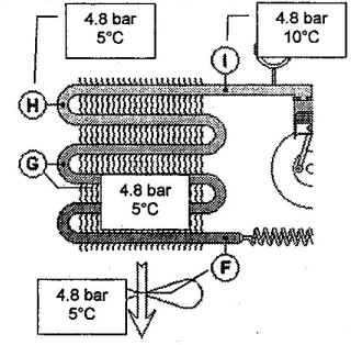
In the example, the temperature of R22 at the evaporator outlet is 1O°C, and the evaporation temperature is 5°C. The value of the superheat is, therefore, 10°C – 5°C = 5K.
From now on, we must remember that refrigerant vapour is several degrees superheated before it goes into the compressor.
So, we can be certain that the compressor only ever draws in vapour and never liquid. If liquid does reach the compressor, we’d have the “liquid hammer” or “liquid slugging” problems that will damage the compressor.
For now, let’s say that “liquid hammer” results in insufficient lubrication of the compressor and that it may even end up purely and simply destroying the compressor valves!
Now let’s look at the diagram, which summarises the changes occurring in the refrigerant as it passes through the evaporator.
You’ll notice that, unlike the condenser, the evaporator has only two distinct zones: the evaporation zone and the superheated zone.
Note that with a superheat of 5°C, the superheated zone only represents about 3% of the total capacity of the evaporator, that is, only a very small proportion of it.
However, superheat is very important in the analysis of the performance of a refrigeration system. In addition, it’s straightforward to measure, and it’s really useful in helping us know how well an air conditioning system is operating and diagnosing faults.
Now we’ll look at what happens to the air as it passes across the evaporator.
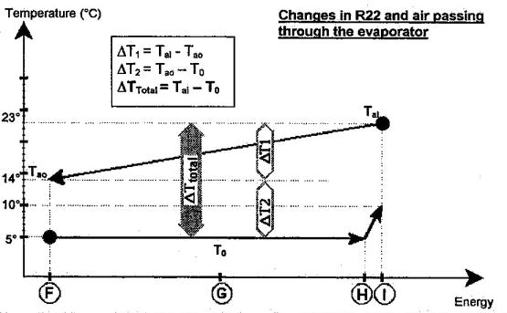
The diagram below shows that the air gradually cooled as the refrigerant evaporated.
We are interested in the following temperatures.
- To: We are interested in the following temperatures
- Tai: Temperature of the air at the inlet of the evaporator
- Tao: Temperature of the air at the outlet of the evaporator
You’ll notice that the refrigerant and the air are in counter-current flow in the evaporator to optimise heat exchange.
In a comfort air conditioning system, the temperature differences are as follows.
The temperature difference (ΔT) between the inlet end and the outlet is between 8 and 10K.
In our example, ΔT for the air is 14°C – 5°C = 9K.
The temperature difference (ΔT) between the air outlet and the evaporation temperature is between 8 and 10K.
The temperature difference of most interest to us is between the evaporation temperature and the air inlet temperature. This difference is known as ΔT total for the evaporator. It is generally somewhere between 16 and 20°C. In our example, ΔTtotal is 23°C – 5°C = 18K.
In a comfort air conditioning system, the temperature differences are as follows.
The temperature difference (ΔT) between the inlet end and the outlet is between 8 and 10K.
In our example, ΔT for the air is 14°C – 5°C = 9K.
ΔTtotal is the difference between the air temperature at the evaporator inlet and the evaporation temperature (read from the LP gauge).
Therefore, the value of this ΔTtotal is a very useful quantity to know.
It’s straightforward to measure the ambient temperature, so with an average ΔTtotal at the evaporator, say 18K, and knowing the room temperature is 25°C, the evaporation temperature should be somewhat 25°C – 18°C = 7K.
So when you connect the LP gauge, the evaporation temperature should be about 7°C. If it’s much more or much less than this, you will know that something is wrong.
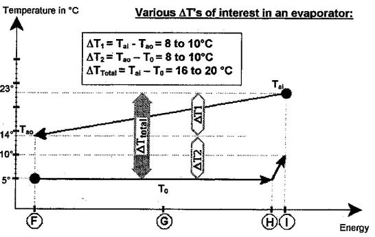
In summary, the LP depends on the air temperature at the evaporator inlet. Similarly, the condenser HP depends on the air temperature at the condenser inlet. So altogether, it’s not as complicated as all that!
Back to Basic!
Related
Read more: Fan wall
Read more: How to verify the percentage of outside air in an enclosure
Read more: BCA Part J5 Air-conditioning system control
Read more: Microbial Induced Corrosion (MIC) in Pipes
Read more: Is your kitchen exhaust system a fire hazard
Read more: What is coanda effect
